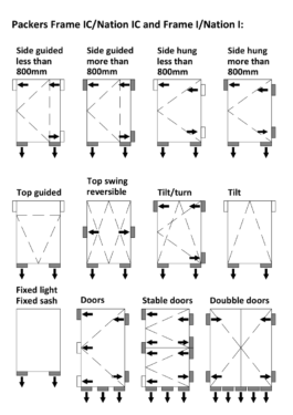
Frame I Turn/Tilt Window
- Product information:
- Eref: +2,9 (Medi g) | +13,3 (High g)
- Uw: 0,82 (Medi g) | 0,85 (High g)
- Glass dimensions: Triple glazing (48 mm): 4-18-4-18-4
- Styling bar: 22/23 mm og 42 mm
- Frame dimensions: 50 x 122 / 149 mm
Use
Turn-tilt windows are often used in multi-storey buildings or where external sun protection is installed. Frame I / Nation I (inward-opening) and Frame IC / Nation IC (outward-opening) have the same exterior frame height and can therefore be placed in the same facade, without there being much visual difference.
The turning function is used primarily in connection with cleaning the outside of the window, while the tilting function is used for daily ventilation and venting. The turning function can also meet all the building regulations' requirements for rescue openings.
Function
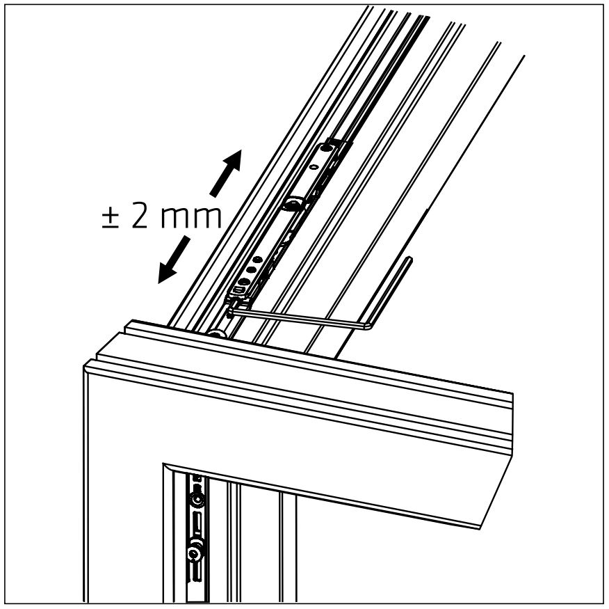
The turn-tilt window is an inward-opening window with both side- and bottom-hung function. Both opening functions are controlled by the fitting lever in the side frame. In the closed position, the handle faces vertically downwards and the turning function is triggered by turning the handle 90° to the horizontal position. The tilt function is triggered by turning the handle 180° in an upright vertical position. With tilt function, the upper edge of the frame moves approx. 14 cm inwards and gives a free opening of approx. 4 cm.
The turn-tilt window can, as an option, be supplied with a handle operated brake. The brake can, in the turning function, hold the frame in any position above 18° opening.
Correct installation and maintenance is important to ensure full warranty coverage.
To ensure that the windows and doors function and operate optimally, it is important that they are installed correctly. Incorrect installation may result in product failure which is not covered by the warranty.
If you have any questions regarding the installation of the elements, please call our Service Department on tel. 01582 860 940. They will be happy to help you.
When unloading and handling the elements, use tools and methods which do not cause damage the elements or the health of those on site.
Upon receipt, the purchaser must check that the consignment complies with the agreement and that the elements are free from apparent defects, faults or transportation damage. If there is any cause for complaint, please notify Idealcombi’s Service Department on tel. 01582 860 940 before installing the elements.
Stickers and cork chips on window glass should be removed 1-2 weeks after receipt. Corner protection, protective films and other packaging must only be removed before installing the elements.
If stored outdoors, the elements must be placed on battens or pallets to keep them clear of the ground. The elements must be covered with a suitable and secure material to protect them from precipitation and dirt. Allow for sufficient ventilation around the elements in order to reduce the risk of condensation forming underneath the covering and excessive heat building up due to direct sunlight. Individual window elements should be stored under a roof structure, in a container or preferably inside.
Our windows and doors are supplied with a small tin of paint in their particular colour. The paint is intended for repairing any minor damage caused during installation, but can also be used subsequently. Idealcombi’s Service
Department is always willing to offer help and advice on surface treatment maintenance and on where to buy additional paint in a particular colour for later use.
Correct installation is important for the function and life of the elements. The installation should therefore be carried out by professional fitters of windows and external doors.
The instructions in this manual cover some of the main issues – but not every detail – which may be relevant during installation.
Back boards on fully insulated spandrel panels are loosely fitted. After installation the cavity is insulated and a damp membrane fitted. Then the back board is sealed and fixed with nails.
The window is usually placed within the outer leaf construction of the wall. It should be fitted centrally giving uniform gaps between the frame and structure – ideally the gaps should be 10 to 15mm. The window should be installed with the frame plumb both
horizontally and vertically and should be adjusted and fixed to ensure the correct closing position between the frame and sash.
Securing, general
Windows and external doors should always be fixed to the building structure using mechanical fixings such as frame bolts / screws.
If any foaming material is used to fill the gap between the outer frame surface and the structure the element must be fixed first using mechanical fixings.
Sealant
The sealant work must be carried out in accordance with sealant manufacturers recommendations and current standards.
When filling gaps with insulation (expanding foam) never put in too much so that it bows the frame. After the expanding foam has cured a waterproof sealant should be applied to the outside (see paragraph on sealant types). To make sure you have enough depth
(in accordance with the sealant manufacturers recommendations) you may have to rake back the expanding foam insulation.
Sealant types
There are a wide range of sealing products to choose from for use between frames and outer walls.
The two most common types are:
– Plastic or elastic mastic
– Asphalt saturated plastic foam (Illmod sealing tapes)
Please refer to sealant manufacturers guide lines to ensure correct product and size before applying.
In order to preserve the wood and reduce heating consumption, it is important that the sealant stays intact. The sealant should therefore be inspected at least once a year, and any flaws should be remedied using the same type of sealant as the original. In case
of any major flaws, all the sealing material must be replaced. In such cases, it must be assessed whether a different type of sealant would be more suitable than the existing one.
Place permanent wedging under jambs and any mullions to ensure that the weight of the window element is supported by the underlying structure (A)
For windows with floating mullions, place wedging under jambs and floating mullion to ensure that the weight of the unit is supported by the underlying structure (A)
The sill must be horizontal and straight. It must under nu circumstances curve upwards or downwards. Place permanent wedging below the jamb at the hinge side of the unit (B). When securing, ensure that the point can absorb compressive forces.
Place permanent wedging at the top of the jamb on the hinge side of the unit (C). When securing, ensure that the point can absorb tensile forces.
Place permanent wedging above the jamb at the closing side of the unit (D); when securing, this wedging must ensure that the point can absorb compressive forces.
For a unit height of above 1600 mm, wedging on both sides at the top of the frame is required.
For increased security and strength a permanent packer can be placed behind ironmongery fix points and locking points.
Jambs should be perfectly plumb and square, and can under no circumstances bow.
During installation, the clearance, i.e. the space between the frame and sash, should be adjusted according to the function of the element. The closing side must be adjusted to provide a tight seal when closed.
The tolerance on diagonal measurements is ±2 mm.
Permanent wedging on the frame head may only be used if the load from any window/door elements above does not subject the unit to stress apart from at the jambs and mullions.
Permanent wedging must be moisture resistant min. 40 mm wide. Depending on the sealant location it is recommended to use anti-slip tape
Wedging material must be moisture resistant, min. 40 mm wide and be placed so that it at least supports the fitting groove.
Depending on the location of the seal, it is recommended that anti-slip tape is used on the wedging material according til the FSO Sealand Guidelines.
When fixing directly through the frame into the building structure locate the fixings in the shaded area shown below. Jambs should be fixed 150 mm from the corners and at a distance of no more than 600mm between fixings. At the head and cill the fixing points can be max 600 mm apart.
For element widths under 600 mm fixings in head and sill can be omitted.
It is recommended that headed screws are used when fixing and that the profile is countersunk for the screw head.
Place permanent wedging under jambs and any mullions to ensure that the weight of the window element is supported by the underlying structure (A)
For windows with floating mullions, place wedging under jambs and floating mullion to ensure that the weight of the unit is supported by the underlying structure (A)
The sill must be horizontal and straight. It must under nu circumstances curve upwards or downwards. Place permanent wedging below the jamb at the hinge side of the unit (B). When securing, ensure that the point can absorb compressive forces.
Place permanent wedging at the top of the jamb on the hinge side of the unit (C). When securing, ensure that the point can absorb tensile forces.
Place permanent wedging above the jamb at the closing side of the unit (D); when securing, this wedging must ensure that the point can absorb compressive forces.
For a unit height of above 1600 mm, wedging on both sides at the top of the frame is required.
For increased security and strength a permanent packer can be placed behind ironmongery fix points and locking points.
Jambs should be perfectly plumb and square, and can under no circumstances bow.
During installation, the clearance, i.e. the space between the frame and sash, should be adjusted according to the function of the element. The closing side must be adjusted to provide a tight seal when closed.
The tolerance on diagonal measurements is ±2 mm.
Permanent wedging on the frame head may only be used if the load from any window/door elements above does not subject the unit to stress apart from at the jambs and mullions.
Permanent wedging must be moisture resistant min. 40 mm wide. Depending on the sealant location it is recommended to use anti-slip tape
Wedging material must be moisture resistant, min. 40 mm wide and be placed so that it at least supports the fitting groove.
Depending on the location of the seal, it is recommended that anti-slip tape is used on the wedging material according til the FSO Sealand Guidelines.
When fixing with brackets, these must be fixed in the marked area.
Fixings in the jambs 150 mm from a corner and with a maximum spacing of 600 mm.
At the head and sill there can be a maximum of 600 mm between fixings.
For element widths under 600 mm fixings at the head and sill can be omitted
Coupled units have a mutual distance of 8 mm. In the rebate, the units are joined together with 5×60 mm wood screws. A silicon seal must be applied between the window units and the coupling strip. Exterior seal with silicon or Compriband.
Adjoining elements should have a spacing of 8 mm. Join the elements together in the rebate using 5×50 mm wood screws. Apply mastic between the window units and spacer strip/cross tongue.
Seal outside using mastic or compriband.
At the jamb and head, the seal can be moved to the front of the aluminium frame.
Drainage happens at the sill between the wood and the aluminium. The seal under the sill must therefore be placed on the wood part, as shown on the drawing.
After installation all drilling dust is removed and locking points are lubricated. This will ensure long lasting trouble free operation.
Weather seals can be rubbed with a silicone stick.
The sash rests on a pin at the bottom of the hinged side, allowing vertical adjustment.
The sash rests on a pin at the bottom of the hinged side, allowing horizontal adjustment of the sash. The sash is guided by levers in the frame head, allowing horizontal adjustment of the sash.
The mushroom bolts can be adjusted at any time to increase or decrease the tightness of the weather seals.
When closed, the sash is held up by a sash support. The sash support can be adjusted vertically to avoid the sash from dropping.
The button must be pushed in to turn the handle.
Handle operations can be locked when the window is closed.
This website uses cookies so that we can provide you with the best user experience possible. Cookie information is stored in your browser and performs functions such as recognising you when you return to our website and helping our team to understand which sections of the website you find most interesting and useful.
Strictly Necessary Cookie should be enabled at all times so that we can save your preferences for cookie settings.
If you disable this cookie, we will not be able to save your preferences. This means that every time you visit this website you will need to enable or disable cookies again.
This website uses Google Analytics to collect anonymous information such as the number of visitors to the site, and the most popular pages.
Keeping this cookie enabled helps us to improve our website.
Please enable Strictly Necessary Cookies first so that we can save your preferences!